Geometric Design Of Highways Video

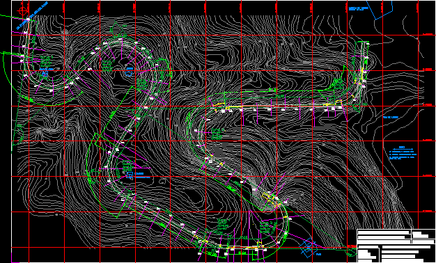
The geometric design of highway includes the principle elements of highway alignment, x-sections and adjacent road side environment. The three dimensional physical location determined through calculation of horizontal and vertical alignment of highway centerline, based on variety of operational considerations results in the geometric design and represent all visible features of highway or street.
Controls and Criteria for Geometric Design
- Design Vehicles
- Passenger cars, buses, trucks, RVs
- Physical characteristics: weight, dimensions
- Establish intersection radius, pavement markings
- Vehicle Performance
- Operating characteristics: accel/decel
- Impacts air quality, noise, land use
Driver
- Information handling
- Reaction time
- Time to perceive + react to a hazard in vehicle's path
- Expected/unexpected
- Speed
- Driver errors
- Traffic
- Composition and volume
- Average daily traffic (ADT) is not adequate
- Design hourly volume (DHV)
- 30th-highest hourly volume (30HV) in one year
- K-factor (% of ADT; 8~12% urban, 12~18% rural)
- Speed of the vehicles
- Operating Speed (typically the 85th percentile speed)
- Free-flow Speed (close to zero density)
- Running Speed (actual speed)
- Design Speed (as high as practical)
- Capacity
- Maximum hourly flow rate (per lane) under prevailing conditions
- Determines adequacy of existing roadways
- Helps select roadway type
- Helps define needs
- Design level of service (LOS)
Design Speed
It is defined as;
- A selected speed used to determine the various geometric features of the roadway that influence vehicle operation.
- It is the measure of the quality of design offered by the road.
- It is sometimes considered to be "The highest continuous speed at which individual vehicle can travel with safety on a road traffic density is so low that the safe speed is determined by the geometric features of the road".
- Design speed sets limit for curvature,, sight distance, and other geometric features.
- It is preferable to use a constant design speed for assuming constant road features. A change in design speed should be made over a sufficient distance to permit drivers to change speed gradually.
- Design speed varies from 30 - 130 km/hr in an increment of 10 km/h.
Design Vehicle
Based on dimension motor vehicles are divided into various design classes, as each dimension affect the design of road in a specific manner such as:
Width of vehicle (effects) width of traffic lane
Length of vehicle ==> Roadway capacity and the turning radius.
Height ==> clearance of various structures
AASHTO divides the design vehicles in four classes;
- Passenger cars
- Buses
- Trucks
- Recreation vehicles
The different dimensions of vehicles are:
H ==> 4.25 to 13.5
W ==> 7 to 8.5
L ==> 19' to 104.8'
Stopping and Sight distance
It is the sum of the two distances.
- Lag distance : - The distance traveled after the obstruction comes into view but before driver applies the brakes. It is also called Total Reaction Time. Which may be split into two parts.
- perception time : - Is the time required to alert the driver before reaction can began.
- Reaction time : -Is the time after the person\s eye register a given happening, and is the period elapsed before muscular reaction occurs.
Perception and reaction distance = tv = 1.47v
- Breaking distance = v2/(2gf) = V2/(254f)
Length of roadway that should be visible ahead of you in order to ensure that you will be able to stop if there is an object in your path.
Calculate the SSD for a vehicle traveling on your roadway at the design speed, and then make sure the actual sight distance that you provide is at least as great as the stopping sight distance
- Assume
- Driver eye height of 3.6 feet
- Height of object between 2.0 and 3.6 feet
- Reaction distance + braking distance
- Design standard: tr=2.5, a=11.2
Other sight distances
- Decision sight distance
- Allow longer tr for information processing for different maneuver conditions (table 6-5)
- Passing sight distance
- Ensure safe passing maneuver (figure 6-5)
- 4 distance components (figure 6-6)
- At 70 mph
- SSD = 730 ft
- DSD = 1445 ft (maneuver E)
- PSD = 2480 ft
Horizontal Alignment
Basic controlling expression
e = rate of superelevation
u = side friction factor (dep. on pavement, speed, …)
V = vehicle speed
R = radius of curve
Vertical alignment (grade line)
The grade line is a series of straight lines connected by parabolic vertical curves to which the straight grades are tangents known as profile grade line.
Overall design procedure
- Determine a reasonable maximum super elevation rate.
- Decide upon a maximum side-friction factor.
- Calculate the minimum radius.
- Iterate and test several different radii until you are satisfied with your design.
- Make sure that the stopping sight distance is provided.
- Adjust your design if necessary.
- Design the transition segments.
Super Elevation of roads
-
Tilting the roadway to help offset centripetal forces developed as the vehicle goes around a curve
- General Practice
- Highways, no ice/snow
emax = 0.10 - Highways, snow/ice
emax = 0.06 - Traffic congestion or roadside development, limit speeds
emax = 0.04 ~ 0.06
- Highways, no ice/snow
Side Friction
Design based on point where centrifugal force creates feeling of discomfort for driver
| Speed | u max | u design |
| 20 | 0.50 | 0.17 |
| 30 | 0.35 | 0.16 |
| 40 | 0.32 | 0.15 |
| 50 | 0.30 | 0.14 |
| 60 | 0.29 | 0.12 |
| 70 | 0.28 | 0.10 |
Let us know in the comments what you think about the concepts in this article!
Geometric Design Of Highways Video
Source: https://www.aboutcivil.org/geometric-design-of-highways.html
Posted by: ackerfainjusly.blogspot.com

0 Response to "Geometric Design Of Highways Video"
Post a Comment